RDT Packet Decomposition
Introduction:
I am currently a senior in computer science at UCSB. I've been working at Ericsson over the last year. During my junior year at UCSB I decided that it was time to learn more about the computer industry. A friend of mine worked at Ericsson and gave my resume to the Director of Carrier Access Products. At this point in my academic career I had taken my data structures classes, algorithms and theory courses. I had not taken Software Engineering, Compilers, Databases, Networks, Operating Systems, or any of the classes that give you a good look at the different areas one could specialize in. I knew that I could program, but I didn't have any clue to what I wanted to program. I was looking for a place to learn about the computer industry. I was open to doing any kind of work that would show me how software development takes place in companies today. Ericsson employed me to do testing on their code. This was a great opportunity to learn how things worked in today's industry.
At Ericsson there are several different layers of testing (Quality Assurance, Integration Testing, etc.). My job was to actually work with the engineers who are developing the embedded c-code and routines for Ericsson routers. My first job was to setup an area for bulk testing external modems. I had to hook 128 modems to a Linux box and write the scripts to make calls with 128 modems at the same time from one PC. Next, I started setting up all of the physical connections using E1/T1 Channel Banks for the modems to call out on. Then came learning the routers so that I could configure the E1/T1 Interfaces, load the code onto the routers, and configure user information used by the modems for negotiations. Finally, I would run tests on the newly developed code. In completing this task I learned about networking (physical and software aspects), code development (the code base), signaling (physical mediums to transfer data), and writing scripts. The simple task of testing modems drove my interest in a network-based direction.
Demand for Remote Debugging Tool:
The testing that I performed help detect conditions and problems that arose when certain modems attempted to connect to Ericsson's Routers. Debugging modem issues is not an easy task. These problems take place on the modem card at the Digital Signal Processor (DSP) level in the hardware. A hardware-based debugging tool was the only in-house tool used to debug signaling and DSP level problems. This hardware setup is expensive and needs to be implemented in a PC located near a router. It is quite a hassle just to set up this hardware-debugging tool. It contains two separate cards (TIM/TICK), a special connector to connect to the router and software to run on the PC. This setup is used to catch events, statements, and variables that engineers generate in their code.
I was assigned to develop a new Remote Debugging Tool to help engineers debug problems at the DSP level. The goal of the Remote Debugging Tool is to catch the events that are generated in the code and capture the events on any available PC. The name of this project became Remote Debugging Tool (RDT). This RDT would be completely independent of any hardware. One advantage of RDT is that with software located only on a PC here in Santa Barbara, we could capture events and actual training sequences of modems connecting to a router that was located anywhere in the world. It will work as long as the router is connected to the Internet and not behind a firewall.
Remote Debugging Tool:
Remote Debugging Tool (RDT) is like most other network-based applications. There is a server and a client side of RDT. The server side was embedded into the C-code that sits on a router. There was already code setup to generate events and send variables to the hardware setup. For Remote Debugging Tool these events are collected, stuffed into packets and sent across the network. The client side of RDT was developed in Java. The client captures the packets, then formats and displays the packets for the user. The connection used to pass information is a standard tcp socket. Built on top of this socket, I developed header information that was used to configure the Remote Debugging Tool. The configuration packets allowed the user (on the client side) to actually specify and filter events as needed. The actually data that is sent across is referred to as events or traces. These events also have a specific format, allowing the engineer to send the values of any variables he/she wishes to monitor. Remote Debugging Tool has become one of the primary ways to debug a problem.
RDT Features:
Remote Debugging Tool has a couple of features for capturing different
types of traces (debugging information). Only one Client session
at a time is allowed to take place. The User Interface is implemented
on the client RDT application. User Interface includes the following
options:
· Select DSPs
· Set Filtering Command List
· Save
· Purge Data
· Start/Stop
· Enable PCM/Disable PCM
· Enable RawMode/Disable RawMode
· Enable LapmSnoop/Disable LapmSnoop
To capture a simple trace, the user must select the DSP and fill in
some commands on the filtering list prior to selecting start. To
select the DSPs, the user should know which modem pool that he/she is going
to call into on the router. This is important because if the user
monitors DSPs 1-24 on slot 1, but all the modem calls are routed to slot2,
then the engineer will not receive any trace information. The filtering
list only has two commands. An engineer can enter multiple commands
into the command line. The standard convention for filtering commands
is [s,c] event# sub-event#. The s is used to set, and the c is used
to clear. There are 255 events, and each event can have up to 64
sub-events. An example command list would be:
S * * //capture all events
C 137 2 //do not send event 137, sub-event 2.
Following the selection of the dsps and the filtering list, the user
may select start and begin capturing dsp-generated events.
Saving and purging of data are two functions that can only be used while the client is not communicating to the router. Purging was determined to be done only when the user is not looking at activate traces coming through the network. The purging cleans all queues and buffers on the client side. There are actually two different types of saving. One saving operation is saving PCM information, which will be explained later in this document. The other save operation saves the existing information in the data area of the client gui. Again, during a save the data area may not be allowed to capture new information, so the tracing must be stopped to be able to save traces.
When an RDT Trace is received by the client application, the data from the event is put through a decoder that formats the data. Many of the events are predefined in the code. A decoder in the client uses the event number and sub-event number to know when to print data as a string of characters, versus a short or long integer. This gives the engineers the ability to send anything from char strings, int, bytes, shorts, or words depending on the variable he/she wishes to monitor in the trace. Raw Mode can be used to disable this decoder. When Raw Mode is enabled, captured traces are displayed as raw bytes in hex-decimal format. Raw Mode is often used for variables that have varying sizes that the decoder can't correctly predict. Raw Mode is also often used when an engineer creates a new event that has not been appropriately defined for formatting in the decoder.
PCM Mode is another useful feature in Remote Debugging Tool. When enabled, this feature tells the router to write a specific parameter to the dsp. This parameter enables the dsp to save and send the raw pcm bytes capturing from the analog signal produced by the modem. Two pcm bytes create one sample (rx, tx). Each RDT Pcm Packet contains 32 samples or 64 bytes of pcm data. When pcm data is being captured about 4,000 samples are generated each second. So, 20secs of pcm data is 80,000 samples and 160,000 bytes of raw pcm collected from the dsp. Since Pcm data comes at a fast rate, this information is saved straight into a file. If the user selects Pcm Mode �on�, the user is prompt to specify a file for the pcm data when �start� is selected in the application. When �stop� is selected, the pcm file is closed and the save is complete. Pcm samples are used to recreate the noise that modems make during a call. This pcm data is a real world sample of a modem call with actual line conditions that may have been introduced. Then this real world pcm data can be fed byte by byte into a dsp simulator providing more accurate debugging environment.
Lapm Snoop is a variable in the modem code that determines the verboseness of lapm-generated events. When the value is 0, it is set to �off� and no lapm snoop events are generated. The value of 4 is the most verbose setting, generating events in every function entered in the code. The compression can generate an enormous number of events. Even when the events are filtered out, they are still created and can have a performance cost on the modem card. So it was determined necessary to keep Lapm Snoop events from ever being generated through usage of a Lapm Snoop parameter.
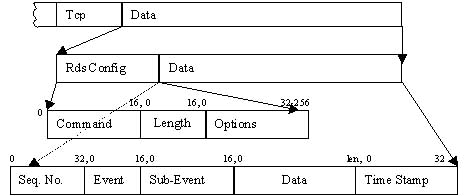
RDT Application Packet Formats:
RDT Application Packet Formats sit at the application level of the TCP/IP stack. TCP was chosen to be the mode of transferring RDT information. UDP was not chose because it was determined unacceptable to lose packets that may contain important information. There are actually two levels of formats for RDT Application Packets. The first layer is the command/configuration header. The second level is the data information, which is separated into sequence number, event, sub-event, data, and timestamp.
RDT Packet Decomposition
Commands
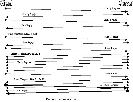
All requests are made from the client. The RDT server originates
all replies.
Communication Sequence Model
RDT Performance and Maintenance Issues:
At the completion of RDT there are performance and maintenance issues that need to be handled. Thoroughly testing the performance raised a couple of issues. To test the Remote Debugging Tool I setup a router on a separate subnet different from the PC that was going to run the client. To get from the PC to the router, an ip packet had to travel across three networks.
Test Setup
The tests took place across two hops on the network. One of the networks the data passed through is a test network that is heavily congested. I noted a couple different observations. While monitoring 20 calls at once, packets begin to get drop from the router because the ring on the router is full. This leads us to conclude that a user should not do more then 20 calls if he/she wants to capture all the data from these traces. Also that if the packets are being sent across more hops with bigger delay the user should decrease the number of simultaneous calls. The next phenomenon occurs when Pcm sampling is enabled, the user should only do 1 call at a time. Pcm samples generate so much traffic that a couple of calls will bog down the modem card so much that it actually has to reset. Once in a while the control card does a status poll, and if the modem card is too busy to answer the poll within a certain time (a timeout occurs) then the control card issues a reset. Remote Debugging Tool does not affect users calling in and connecting to the internet while the dsp they are using is being monitored.
The other maintenance issues are added features and fixes in the future. One important fix for the future is when a modem card crashes, the modem card needs to finish sending out the events before dumping out the crash log and rebooting. Sometimes engineers add new features, and like all areas of development new crashes come along with new development. These crashes are always fixed before any release of the code. However, since RDT is an in-house tool sometimes these untested builds will bring down the modem card while RDT is being used to test the builds. Then the client will get in a state of waiting for a reply that is not going ever be created since the router has gone down. A timer needs to be developed so that the Java application will timeout if the socket is killed without a proper tcp closure sequence. So two cases needs to be handle when the control card crashes. First reminder of trace information needs to be sent. Second the client needs to be more independent of the server.
There will always be a need for other new features. A need to refine the decoder for new features being added to the code. Also similar parameters to turn on or off the generation of events for new features will be needed. Since RDT has become a primary way of debugging our routers, there is also a need to merge into new code bases so that any product that uses dsps can use RDT.
Conclusion:
During my time at Ericsson I have gain valuable industry experience.
I've gotten a first hand look at how the need for a better solution to
a problem develops into a program. I've also learned an enumerable
number of little things that are very important. Things like designing,
coding, finishing a project, scripting, network configurations, vi commands,
and more. I am continuing to work with Ericsson after school and
learn new and exciting things every day.