ABOUT
ME
In November of 1998 I began
an internship with a company named Advanced
Computer Communications (ACC). Shortly after I began, Ericsson,
A large wireless telecommunications company purchased ACC, and it is now
Ericsson
Datacom. The company continues to focus on the design,
implementation, and distribution of Access Servers, Routers, and other
networking products. It is a fast growing company with great potential
for continued growth especially now that it is under the wing of Ericsson,
a large and well respected company throughout the world, not just the United
States.
Four years of Computer Science
courses through UCSB have provided me with an excellent conceptual knowledge
of the way things work in the computer world, but it has been through working
at Ericsson where I have gained hands on experience in the real world.
My introduction as a software intern has placed me a in a position to write
diagnostic code for our newest enterprise development product. The
engineers in my group are divided between diagnostics and application level
code, and of course hardware and software. We work side by side together
in the lab, and there is plenty of overlap of responsibility. Because
I am an intern, also known as low man on the totem pole, I also pick up
a great deal of additional tasks such as chip programming, cable making,
and general grunt work for other engineers.
My focus, however, is software
and my main task in the development of our new product has been working
with diagnostic and driver code for a new system. I cannot go into
specifics on the product, but the core is a high performance router, with
add on features such as a modem card to provide Remote Access Server capabilities,
or a IP/PBX box for Voice Over IP and telephone management features.
I have learned a tremendous amount through my experience in the development
and debugging of this and other products during my short time at Ericsson
so far. One major responsibility I was given was the configuration
and testing of two on board ethernet controllers, which consisted of communicating
with a new part, and integrating it into the system, as well as interfacing
with the diagnostic menu system and creating and adding a new suite of
tests for the new parts. The Information I would like to present
in this report is an overview and a description of the steps I took in
configuring and testing the Ethernet Controllers in our new system.
OVERVIEW
WHAT
IS A ROUTER?
A router is a device that
connects two or more networks.
OK, but WHAT
IS A NETWORK?
A group of two or more computer
systems linked together is a network. There are many types of computer
networks, including:
Local area
networks (LANs) : The computers are geographically
close together (usually in the same building) and connected with cables.
Wide area
networks (WANs) : The computers are farther apart and are
connected by telephone lines, radio waves, or some other media.
In addition to these types,
the following characteristics are also used to categorize different types
of networks:
Topology : The geometric arrangement of a
computer system. Common topologies include a
bus, star, and ring.
Protocol : The protocol defines a common set of
rules and signals that computers on the network
use to communicate. One of the most popular
protocols for LANs is called Ethernet. Another
popular LAN protocol for PCs is the IBM
token ring network .
Architecture : Networks can be broadly
classified as using either a peer-to-peer or
client/server architecture. |
Network Topologies
|
Computers on a network are
often called nodes. Computers and devices that allocate resources
for a network are called servers. A device that is connected to more
than one network and allows information to transfer between networks is
called a Router. There are many variations of routers and a wide
range of functions that routers can fulfill.
WHAT
IS AN EMBEDDED SYSTEM?
An
embedded system can be defined as a specialized computer system that is
part of a larger system or machine. Typically, an embedded system is housed
on a single microprocessor board with the programs stored in ROM or other
non-volatile storage. Virtually all appliances that have a digital
interface (watches, microwaves, VCRs, and cars) utilize embedded
systems. Some embedded systems include an operating system, but many are
so specialized that the entire logic can be implemented as a single program.
Our
example will consist of many parts which we will not discuss in detail
such as busses that connect components, power supplies, and the like, instead
we will focus on the most significant parts of the system that pertain
to the functionality of a Router, basically consisting of those parts shown
in the diagram in the left.
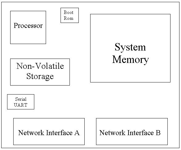
-
Processor - (Intel, Motorola,
MIPS, etc.) responsible for the actual work done in the system.
-
System Memory - Execution
space for the processor and components to work with
-
Boot Rom - Small device
loaded with the initial boot code for bringing up the system
-
Serial UART - Serial interface
for console communication with the system
-
Network Interfaces - Physical
devices for connecting the system to networks
MY
WORK AT ERICSSON
There
is a great deal of designing, manufacturing, and hardware assembly that
must take place before we are presented with a board or system which
we can work with at the software level. The Hardware engineers must
design the physical layout of the system, decide which components to use,
and where to put them, and then stuff everything on the board. Once
the core components are up and running and communicating with each other
properly (Processor, Memory, Boot Device, UART, PCI Bus, etc.) with the
system booting and the Operating System running, then it was time for me
to add the network interfaces and set them up.
The network
interface adapters most commonly used in a system such as this , are PCI
Ethernet controllers. PCI (Peripheral Component Interconnect) is
an industry standard bus architecture that connects the microprocessor
to devices installed in special PCI expansion slots. There are countless
types of devices that can be attached to a PCI bus such as video controllers,
sound controllers, modems, SCSI and IDE controllers, and many more.
Ethernet is a LAN protocol that uses either a star or bus topology.
Standard Ethernet supports data transfer rates as fast as 10mb/s (megabits
per second), and today there exists two new and improved variations, Fast
Ethernet which can support up to 100mb/s, and Gigabit Ethernet which can
support up to 1,000 mb/s.
We will
be using two Fast Ethernet Controllers from AMD which can operate at either
10mb or 100mb and will auto detect which speed to run. The first
step I took in communicating with a new device on the PCI bus, is to run
what are called PCI configuration cycles on the bus. These industry
standard cycles allow us to talk to the new device and read some information
about the device through its PCI registers, such as Vendor ID, Device ID,
the PCI Command Register, and the Status Register. The Vendor id
is used to identify the manufacturer of the device, and the Device id is
used to uniquely identify the particular model of the device. The
PCI Command Register controls the gross functionality of the device and
is responsible for determining what kind of cycles the device will generate
and respond to. I will write to this register in order to enable
Memory Mapping of the devices registers, and also enable the part to act
a bus master on the PCI bus.
Memory
mapping is a term used to describe the access to random areas throughout
the system, as set up to look like plain memory accesses. By this
I mean we can access the numerous registers inside this part on the PCI
bus, the same way we can access main memory, simply by setting up a mapping
between memory addresses and external physical memory space. The
advantage of this is convenience. Now we can easily read and write
values in a register within a peripheral device, just as easily as we could
read or write a standard memory location.
Bus Mastering
is a function that can be performed by intelligent devices that have DMA
(Direct Memory Access) Controllers built in, such as our network interface
adapters. DMA is the ability for a device on the PCI bus to take
control of the bus and access memory without the control of the processor.
The advantage to this is (1) less overhead for the processor, and (2) greater
parallelism within the system as it is possible for several components
to work together concurrently as opposed to serially. By enabling
the device to be a bus mastering device, we are granting it the ability
to always be ready to transmit or receive without worrying about waiting
for the processor to arbitrate the bus for all data transfers.
Once
we have the device in our memory map, we gain access to all the registers
in the part, of which there are often many. With the ability to read
and write registers directly we can now setup the device to work exactly
how we want it to by customizing the values in the various setup CSR (Control
and Status Registers) registers. I had to work closely with the manual
and data sheet for the device and pick and choose which registers to modify,
and then do so accordingly. Once we have located the device on the
bus, and enabled it to enable memory mapping and bus mastering, it is time
to move into the testing and diagnostics phase.
Our diagnostics
run through a special menu system which is separated into packages.
Each package has it own sub menu with its own set of tests and options
for tests. The first thing I needed to do was to create a new Package
for the Ethernet controllers. All my coding will be done within this
new package, and the end result will be that all my tests will be launchable
through the main diagnostics menu.
The first
test that I generally like to run against any new device is a simple
slave register test. This is a test that is used to make sure that
it is in fact possible to read and write registers located in the part.
This can be accomplished in numerous ways, but the basic idea is to find
a register or a set of registers that do not have an effect on the core
functionality of the part (usually there are many test registers built
into a part) and so we want to write arbitrary values to these locations.
Next we go back through the same locations and read the information back,
if the data we read is the same as the data we just wrote, then I have
successfully written and passed the first test.
The next
logical step for an intelligent part such as this, is a bus mastering test.
This will test the parts ability to not only receive information across
the bus, but also to take control of the bus and initiate data transfers
across it. This can generally be accomplished through a special built
in function called an initialization routine. Rather than programming
each of the devices registers directly I can take advantage of this initialization
routine, and allow it to program the part for me. The test will basically
consist of filling a memory location with the values we want to load into
some specified registers, and setting the value of the appropriate location
register(s) to point to that memory location. After I have set these
values, I simply tell the part to initialize (by setting the init bit in
a Control Register) and it will attempt to Take control of the bus, access
the memory location pointed to by the internal register(s), and transfer
the information across the PCI bus from memory to the appropriate
registers in the device. If I set the values correctly and with the
proper offsets this test will also pass, confirming that the device can
function properly as a bus master.
The final
set of diagnostic tests I need complete will be Reliability and Stress
tests which will be used to ensure that the part can function properly
under strenuous activity. First I will need to setup some very important
data structures called Descriptor Rings, in order for our part to function
properly. A descriptor ring is basically a circular chunk of memory
that is shared between the PCI device and the processor. By shared,
I mean that both the processor and the part have the ability to read and
write this memory. Of course I would not want to simply share the
memory, we must establish some special bits within each buffer in the ring,
which are to be used to determine current ownership of that buffer.
In the terms of a network adapter we will need to establish a Transmit
Descriptor Ring and a Receive Descriptor Ring. The Transmit Descriptor
Ring then can be visualized as the area in memory where the processor stores
the data that it wants the part to transmit, when the processor has filled
a buffer with data to be transmitted he relinquishes ownership to the device
so that the data may be sucked out of memory and transmitted out onto the
network. The Receive Descriptor then can be visualized as an area
in memory where the Device will store any data that he receives from the
network, and when he fills a buffer he will relinquish ownership of that
buffer to the processor, so the processor can suck up the information and
process it accordingly. The setting and unsetting of the ownership
bits is a relatively simple concept, and for the most part will all be
handled within an interrupt context. Once I have set up these Descriptors
structures in memory, I have all the parts necessary to write the final
tests.
The test
itself will simply consist of setting the part into a loop back mode (either
internal or external), then fill his transmit descriptor with the desired
test pattern or values, and finally tell the part to transmit (pass the
ownership of the filled Transmit Descriptor Buffers to the device).
The result of this should be the Device acquiring control of the bus, sucking
information out of the Transmit Descriptor Ring and sending it out on the
wire, and because the part is in loop back, the transmitted data will then
instantly be received back in by the device, and transferred to the Receive
Descriptor Ring. There are many options for this kind of test variations
in packet size, patterns, and information but the end result should be
the same in any case. If the device is working properly, the information
stored in the Receive Descriptor Ring should be the same as the Information
that was stored in the Transmit Descriptor Ring. When this is the
case I have completed the addition of my new Package, tests and all.
While
the tests and procedures that I am programming into the part may not seem
like a difficult or even important task, the fact of the matter is diagnostics
are an extremely part of any system (and they weren't so easy for me either).
After the completion of the diags, and verification of the functionality
of the parts in the system, the Application engineers can truly begin to
work their magic. They are responsible for tying in with the operating
system (WindRiver's VXWorks in this case), and setting the actual addressing
and routing schemes for the system as a whole.
The diagnostics
are important not only during the construction of a new product, but throughout
development and after release as well. The diagnostic menu serves
as a highly valuable tool in troubleshooting system problems. By
booting the system into diagnostic mode (as opposed to application mode),
we can run system tests on each part of the system individually and as
a whole, in order to track down problems to specific areas, as well as
to distinguish between hardware and software failures.